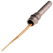
Cal-Stat Thermostats
- Rugged and reliable
- Multiple mounting options
- Corrosion-resistant stainless steel outer shell
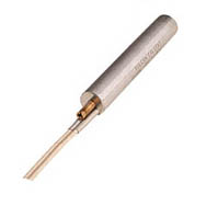
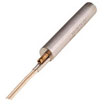
The Vulcan Cal-Stat has been a reliable temperature control for over 35 years. Rugged, self contained Cal-stats provide design and application versatility not found on many mechanical or solid state temperature controls. These units can be inserted into drilled holes or can be directly immersed into fluids or gases when supplied with an appropriate mounting fitting.
- Corrosion-resistant 304 stainless steel outer shell
- 1/2″, and 5/8″ diameter models
- Temperature adjustment range of -100o F (-73o C) to 600o F (316o C) on 1/2″ and 5/8″ models
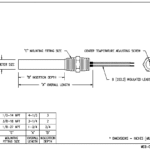
- Adjusting screw mechanism located on center
- Slow make and break switch mechanism
- Amperage switch ratings up to 10 amps depending on model and operating voltage
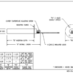
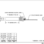
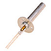
- Standard mounting options include basic cartridge, pipe thread, coupling head, and flange
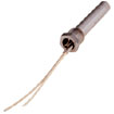
- High temperature lead wire termination – 8″ long
- Many options available including custom lead lengths, temperature presetting, and custom mounting
- Package Machinery
- Commercial Food Equipment
- Lab and Medical Devices
- Laminating Machines
- Marking Equipment
Models and Options
1/2″ Diameter Cal-stat Models
| Construction Details: | |
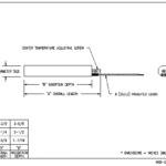
| Diameter: | 1/2″ models: .499 + .000 -.004 (12.7 mm + .000 -.102) 5/8″ models: .624 + .000 -.004 (15.9 mm + .000 -.102) |
| Tube Shell Material: | 304 Stainless Steel |
| Temperature Range: | 1/2″ and 5/8″ models: -100- F to +600- F (-73- C to 316- C) |
| Sensitivity: | As low as 1- F (depending on application) |
| Action: | Slow make and break |
| Switch Rating: | 1/2″ models: 5 Amp @ 120 VAC, 3 Amps @ 240 VAC, 1 Amp @ 120 VDC 5/8″ models: 10 Amp @ 120 VAC, 5 Amps @ 240 VAC, 2 Amps @ 120 VDC |
| Termination | High temperature leads |
5/8″ Diameter Cal-stat Models
| Construction Details: | |
| Diameter: | 1/4″ models: .249 + .000 -.004 (6.3 mm + .000 -.102) 1/2″ models: .499 + .000 -.004 (12.7 mm + .000 -.102) 5/8″ models: .624 + .000 -.004 (15.9 mm + .000 -.102) |
| Tube Shell Material: | 304 Stainless Steel |
| Temperature Range: | 1/4″ models:-100- F to +500- F (-73- C to 260- C) 1/2″ and 5/8″ models: -100- F to +600- F (-73- C to 316- C) |
| Sensitivity: | As low as 1- F (depending on application) |
| Action: | Slow make and break |
| Switch Rating: | 1/4″ models: 1 Amp @ 120 VAC 1/2″ models: 5 Amp @ 120 VAC, 3 Amps @ 240 VAC, 1 Amp @ 120 VDC 5/8″ models: 10 Amp @ 120 VAC, 5 Amps @ 240 VAC, 2 Amps @ 120 VDC |
| Termination | High temperature leads |
| Option Description | Option Code |
| Factory Temperature Setting | A |
| Above 120- F | A |
| 0 – 120- F | A |
| Below 0- F | A |
| Extended Shell Length with Sensitivity at Bottom | B |
| First Additional Inch | B |
| Each Additional Inch | B |
| Extended Shell Length with Sensitivity at Top | C |
| First Additional Inch | C |
| Each Additional Inch | C |
| Tamper Resistant Plug | D |
| Moisture Resistant Seal | E |
| General Purpose Terminal Housing | G |
| Extended Adjusting Screw | H |
| First Inch | H |
| Each Additional Inch | H |
| Optional Lead Lengths Each Foot or Fraction | J |
| Plastic Boot Over Adjusting Screw | K |
| Armored Cable Over Leads | L |
| First Foot | H |
| Each Additional Foot or Fraction of a Foot | H |
| Temperature Calibration Lock (See Option “A” for additional charge for setting) | M |
| Moisture Resistant Terminal Housing | N4 |
| Explosion Resistant Teminal Housing | N7 |
| Extended Adjusting Sleeve | O |
| First Inch | O |
| Each additional inch or fraction | O |
| Special Shell Material | P |
| Special Marking | R |
| Ground Wire | U |
| First Foot | U |
| Each Additional Foot or Fraction | U |
| Blockhead Fitting | BH |
| * Some options may not be available with other option combinations or 1/4″ diameter models. Contact factory for details. |

